Understanding VlanManager Network Flows in OpenStack Cloud: Six Scenarios
- Upon creation, an instance must obtain an IP from a fixed network.
- In general, instances need access to the Internet (to download security updates, etc.).
- Usually instances must communicate within their fixed IP network.
- Some instances need to be exposed to the world on a publicly routable IP.
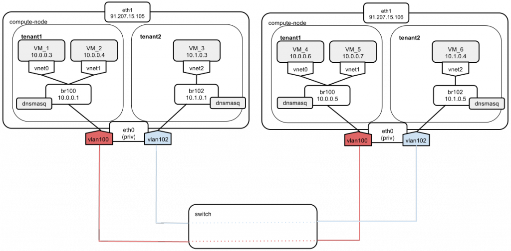
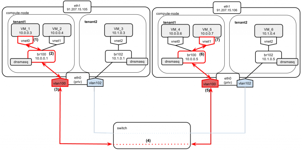
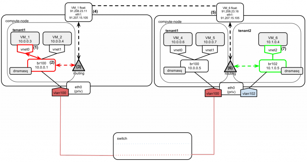
The above diagram shows two compute nodes connected by a network switch.
We have “tenant1” and “tenant2,” which hold different private networks, located in different vlans (100 and 102). Since we are running a multi-host networking setup, every compute node has direct access to external networks (Internet, etc.). For this purpose, an eth1 interface is used. Based on this diagram, I'm going show 6 scenarios that illustrate how different OpenStack networking scenarios are carried out.
Scenario 1
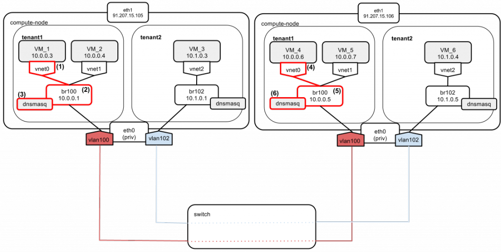
Instances of tenant1 boot up and have their IPs assigned:
- Instance VM_1 boots and sends a DHCPDISCOVER broadcast message on the local network.
- The message gets broadcast over br100.
- The dnsmasq server listens on the address of br100 (“--listen-address 10.0.0.1”). It also has a static lease configured for VM_1. It answers with DHCPOFFER containing:
- an instance address: 10.0.0.3 and
- a default gateway pointing to br100: 10.0.0.1.
- Instance VM_4 boots and sends a DHCPDISCOVER broadcast message on the local network.
- The message gets broadcast over br100.
- The dnsmasq server listens on the address of br100 (“--listen-address 10.0.0.5”). It also has a static lease configured for VM_4. It answers with DHCPOFFER containing:
- an instance address: 10.0.0.6 and
- a default gateway pointing to br100: 10.0.0.5.
Scenario 2
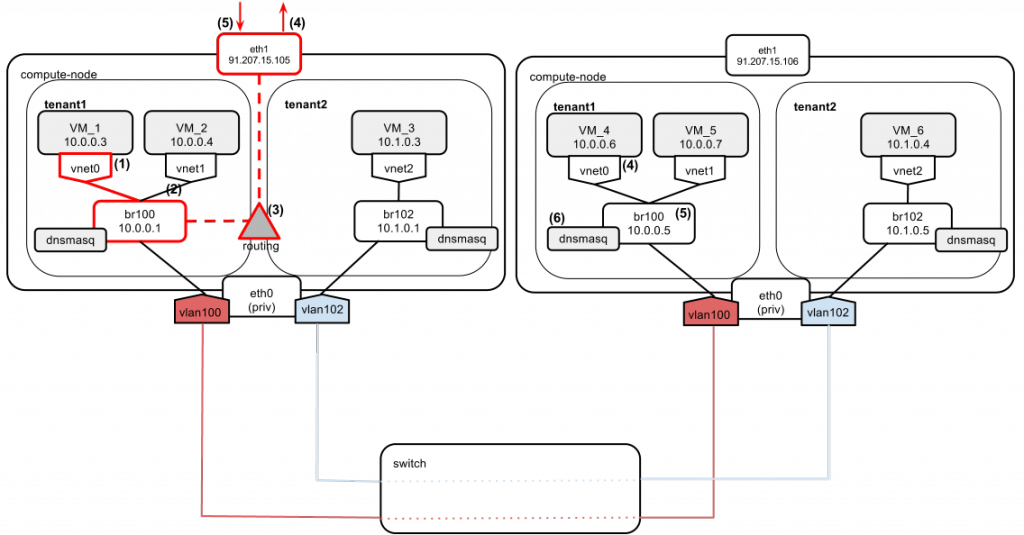
VM_1 wants to access the Internet (e.g., Google's DNS: 8.8.8.8) and it has only a fixed IP assigned.
- VM_1 sends a ping to Google's DNS 8.8.8.8.
- Since google.com is not on its local network, VM_1 decides to send the ping directly via the default gateway (10.0.0.1 in this case).
- Compute node makes a routing decision. 8.8.8.8 does not reside on any of the directly connected networks, so it also decides to send the packet via compute node's default gateway (91.207.15.105).
- On its way out, the packet gets SNAT-ted to eth1's IP: 91.207.15.105. There is a special rule in nova-compute's iptables nat table that handles it:
nova-network-snat -s 10.0.0.0/24 -j SNAT --to-source 91.207.15.105The setting in nova.conf that controls this rule's behavior isrouting_source_ip=91.207.15.105 - 8.8.8.8 sends a reply to 91.207.15.105. The response arrives at 91.207.15.105, and the kernel NAT table is referenced to send the packet back to VM_1.
Scenario 3
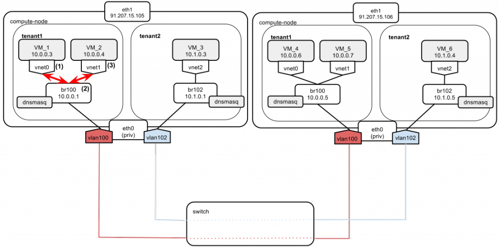
Let’s assume that tenant1 wants to ping from VM_1 to VM_2. We have two important things to note here:
- Both instances belong to tenant1.
- Both instances reside on the same compute node.
Here’s what the traffic is going to look like:
- VM_1 sends a packet to VM_2. VM_2 is on the same net as VM_1. VM_1 does not know the MAC of VM_2 yet, so it sends an ARP broadcast packet.
- The broadcast is passed through br100 to all of tenant1’s network, including VM_2, which sends a reply to VM_1.
- Once the VM_2 MAC is determined, IP packets are sent to it from VM_1.
Note:
Instances of the same tenant live in the same L2 broadcast domain. This broadcast domain expands on both compute nodes via the vlan100 interface and switch, which support 802.1Q vlan traffic. So all ARP broadcasts sent on the tenant1 network are visible on all compute nodes that have the vlan100 interface created. In this case, even if VM_1 and VM_2 are on a single host, the ARP broadcast sent in point (1) is also visible to VM_4 and VM_5.
Scenario 4
Now let’s assume the ping goes from VM_1 to VM_5. Both of them still belong to tenant1, but are located on different physical compute nodes.
- VM_1 wants to send a packet to VM_5, which is located on a different compute node. It sends out an ARP broadcast to determine the MAC of VM_5.
- The broadcast is passed by bridge br100 to all the interfaces it has connected, including vlan100.
- The packet is tagged with 802.1Q vlan tag number 100 on the compute node’s interface.
- The tagged packet goes to the switch. The switch ports are configured in “trunk” mode. Trunking allows passage of vlan tag information between two compute nodes.
- The tagged packet arrives at the physical network interface of the other compute node. Since it bears tag 100, it is passed further to vlan100 interface. The tag is stripped from the packet here.
- Packet goes through br100.
- VM_5 receives the broadcast and replies with its MAC. The reply packet goes the same path in reverse. At this point VM_1 and VM_2 can exchange traffic.
nova secgroup-add-rule default tcp 1 65535 10.1.0.0/24nova secgroup-add-rule default tcp 1 65535 10.0.0.0/24- Instances of both tenants reside on the same compute node.
- Instances of both tenants reside on different compute nodes.
Scenario 5
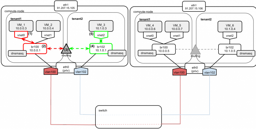
This time the ping goes from VM_1 to VM_3. In this case, packet exchange happens between two tenants. It is critical to understand how the routing between their networks is carried out.
- VM_1 wants to reach VM_3, which belongs to tenant2 and is located on the same compute node. VM_1 knows that VM_3 is on a different network than its own (10.0.0.0/24 vs 10.1.0.0/24), so it sends the packet directly to the gateway, which is 10.0.0.1.
- The packet arrives at br100.
- Compute node routes the packet to br102 based on its internal routing table.
- The packet arrives at br102. VM_3 MAC is determined by ARP broadcast.
- VM_3 replies with its MAC. Since VM_1 is on a different network than VM_3, VM_3 sends the reply to the default gateway, which is 10.1.0.1 (the address of br102). The packet is then routed back to tenant1’s network via br100.
10.0.0.0/24 dev br100 proto kernel scope link
10.1.0.0/24 dev br102 proto kernel scope link
Scenario 6
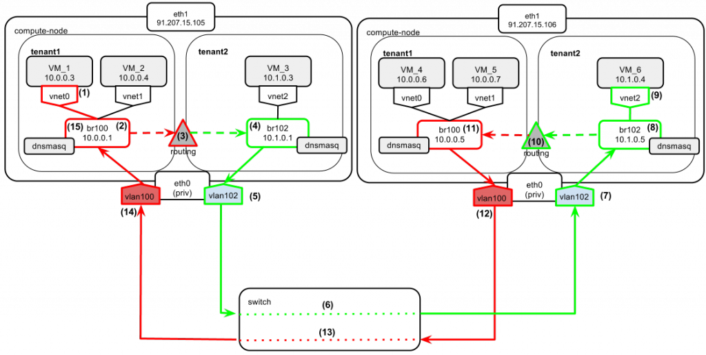
This time the ping goes from VM_1 to VM_6. They both belong to different tenants and reside on different compute nodes. Pay special attention here to observe the “asymmetric routing” (i.e., requests from VM_1 to VM_6 go one way, but the response from VM_6 to VM_1 takes a different route).
- VM_1 wants to exchange data with VM_6. VM_6 belongs to a different tenant and is located on a different compute node. Since VM_6 is not on VM_1’s local network, VM_1 sends the packet with the target address 10.1.0.4 directly to the gateway, which is 10.0.0.1 in this case.
- The packet from VM_1 arrives at br100.
- Compute node sees the target network (10.1.0.0/24 belonging to tenant2) on br102 so it routes the packet to br102.
- The packet is now on tenant2’s L2 network segment.
- It gets its 802.1Q vlan tag.
- It goes through the switch trunk ports.
- The tagged packet arrives at the physical network interface of the other compute node. Since it bears the tag 102, it is passed further to the vlan102 interface. The tag is stripped from the packet here.
- The packet goes through br102 and reaches VM_6.
- VM_6 sends a reply to VM_1 with a destination address (10.0.0.3). Since VM_1 is located on a different subnet, the reply is sent directly to the default gateway, which is 10.1.0.5 in this case.
- The compute node sees the target network (10.0.0.0/24 belonging to tenant1) on br100 so it routes the packet to br100.
- The packet is now on tenant1’s L2 network segment.
- It gets its 802.1Q vlan tag.
- It goes through the switch trunk ports.
- It arrives at the physical network interface of the left compute node. Since it bears tag 100, it is passed further to the vlan100 interface. The tag is stripped from the packet here.
- The packet goes through br100 and VM_1 gets a reply back.
But what about this one?
OpenStack provisions networks “on demand”. This means that if you create a new network in openstack, the setup for it (i.e. dedicated bridge plus a vlan interface) is not propagated across all compute nodes by default. It's only when an instance to be attached to a new network lands on the compute node that the network is actually bootstrapped. So it is common to have differences in network configurations between compute nodes. For example, on one compute node there could be br100, br102, br103 set up, while on another there could only be br102 present.
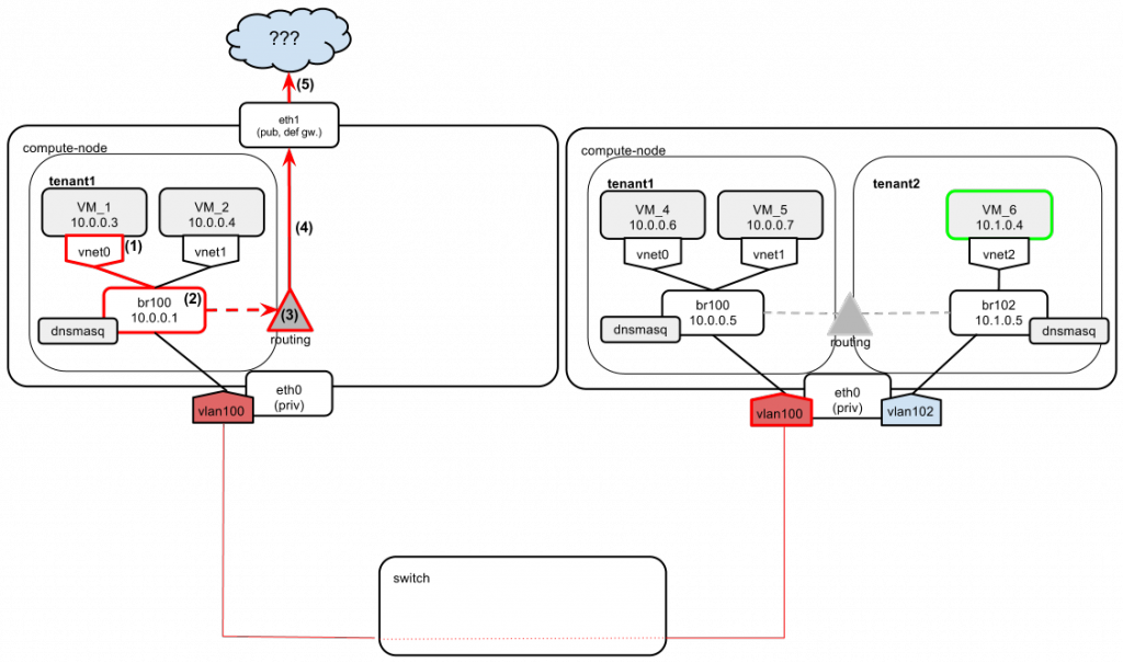
Such behavior may lead to a frustrating situation. Imagine we want to ping VM_1 to VM_6 again. But this time we have no tenant2 instances running on the leftmost compute node (so no bridge br102 and no vlan102 are present). But wait a minute — since bridge br102 was acting as a gateway to network 10.1.0.0, how do we get to tenant2’s network? The answer is simple — by default we can’t!
- VM_1 wants to send a ping to VM_6, which is on a different network than VM_1 itself.
- So VM_1 sends the ping to the default gateway (br100, 10.0.0.1).
- On the compute node there is no direct route to network 10.1.0.0 (there is no br102 yet, which would provide one).
- So the compute node sends the packet to its own default gateway, which happens to be eth1.
- Since eth1 is on a completely different wire than eth0, there is no chance of finding the way to 10.1.0.0. We get a “host unreachable” message.
We now can see that intertenant connectivity cannot be ensured by relying only on fixed IPs. There are a number of potential remedies for this problem, though.
The simplest way (and the best in my opinion) would be to place the intertenant communication on floating IPs rather than on fixed IPs:
Scenario 7
VM_1 wants to send a ping to VM_6. Both instances have floating IPs assigned. Given our understanding of how floating IPs work from the previous post, it is clear that these IPs will be attached as secondary IP addresses to eth1 interfaces on compute nodes. Let's assume that the following floating IP pool was configured by the cloud administrator: 91.208.23.0/24. Both tenant1 and tenant2 allocated themselves addresses from this pool and then associated them with their instances in this manner:
- tenant1: VM_1: 91.208.23.11
- tenant2: VM_6: 91.208.23.16
So the situation is now as follows:
Let's say VM_1 wants to ping VM_6. Tenants use their floating IPs to communicate instead of fixed.
- VM_1 wants to ping VM_6, whose floating IP is 91.208.23.16 . So the ping goes from source 10.0.0.3 to destination 91.208.23.16.
- Since 91.208.23.16 is not on VM_1's local network, the packet is sent with destination address 10.0.0.1, VM_1's default gateway.
- The compute node makes a routing decision to let this packet out via eth1.
- Source NAT-ting (SNAT-ting) of the packet is performed (rewrite of the source address: 10.0.0.3 -> 91.208.23.11). So now the packet source/dest. look like this: source 91.208.23.11 and destination 91.208.23.16.
- The packet arrives at the destination compute node with the source 91.208.23.11 and the destination 91.208.23.16. Destination Network Address Translation (DNAT) of the packet is performed, which changes its destination IP from 91.208.23.16 to 10.1.0.4. The packet source/dest. now look like this: source 91.208.23.11 and destination 10.1.0.4.
- Based on the destination IP, the compute node routes the packet via br102.
- The packet reaches the destination: VM_6.
The response from VM_6 to VM_1 goes the same way, but in the reverse order. There is one difference, though. Since the ICMP reply is considered to be "related" to the ICMP request previously sent, no explicit DNAT-ting is done, as the reply packet returns to the leftmost compute node via eth1. Instead, the kernel's internal NAT table is consulted.
Other ways to ensure proper intertenant communications based on fixed IPs (as far as my knowledge of networking is concerned, and please note — these are only my personal thoughts on the problem) would require patching OpenStack code:
- You could ensure that when a new network is added, the bridge and corresponding vlan interface would be created on all compute nodes (right now it's done only when an instance is spawned).
- An upstream router could be attached to the OpenStack private network (eth0), which could act as a gateway between tenants' networks. Some code however would need to be added to OpenStack to ensure proper 802.1q tagging of the router traffic, based on what vlans are configured for OpenStack networks.
- Use FlatDHCPManager if it fits. This way only one network bridge is created on each compute node and it is there right from the start.
Conclusion
In this post I analyzed various scenarios of instance traffic, starting with the instance's birth and boot-up, ending up on intertenant communication. The current networking model has its limitations and doesn't always function as the user might be expecting. Still, OpenStack is highly flexible and extendable software. It provides users with the means to either tackle these limitations with proper configuration changes or address their specific needs with custom code extensions. Also, Quantum is coming in the next release and will introduce a small revolution to the whole networking concept, which probably means an end to all these pains.
